- upload bom file
- +86 0755-82770375
- info@onepcba.com
- Compare Products
- Change Location:
Introduction to naming conventions for electronic components

Introduction to naming conventions for electronic components
Electronic component naming conventions are used to describe semiconductor devices, passive components, and connectors used in circuit design.
In the electronic component naming convention, the component family is very important for hole naming and surface mount naming.
The lead spacing or positions between holes where the component leads are inserted from the first number in the naming convention for standard through-hole components.
A PCB is a hardware implementation of an engineer-designed circuit. Circuit blueprints are physically constructed using electronic components such as resistors, capacitors, inductors, diodes, and integrated circuits. When all the electronic components are working properly, the desired output can be obtained from the circuit board.
In the PCB design phase, establish the electrical connection between various electronic components in the circuit. The schematic diagram follows certain naming conventions of electronic components for easy understanding and identification. In this article, we will discuss the electronic components used in PCBS and their naming conventions.

Common electronic components
Electronic components are necessary to make PCBS; When electronic components are connected according to a circuit diagram, they form a meaningful PCB. If any of the electronic components fail to perform their role, the board may not achieve the intended function or output.
In PCBS, electronic components belonging to the same class may differ in their type, size, geometry, packaging, or electrical specifications. Here are some common electronic components found in PCBS:
Resistance - The most common electronic component in PCBS. They are used to limit the current in the path. There are different types of resistors available, including carbon film resistors, metal film resistors, and chip resistors.
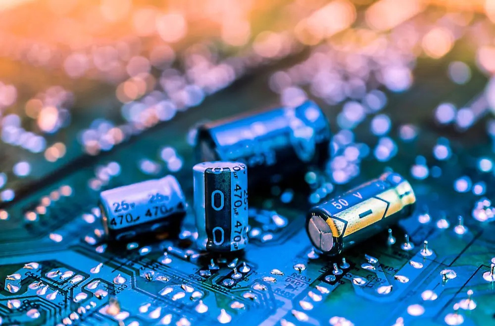
Capacitors - the second most common electronic component in PCBS. Capacitors can be polarized or unpolarized. Some common capacitor types are mica, tantalum, and ceramic capacitors.
Inductors - Inductors are used to store electrical energy in the form of magnetic energy. The simplest inductors can be obtained by inserting a wire into the coil.
Diode - Diodes are semiconductor electronic components used to allow current to flow in one direction while blocking the flow of the reverse current. They are also used for voltage regulation and lightning protection purposes. Commonly used diodes include signal diodes, power diodes, Zener diodes, and light-emitting diodes.
Transistor - A transistor is a three-ended device used as a semiconductor switch or linear amplifier.
Integrated circuits - Most circuit boards require bridge rectifiers, oscillators, amplifiers, and timers. These circuits are provided in the form of integrated circuits.
Transformer - Used for electrical isolation, voltage boost, or voltage drop on circuit boards.
The list of electronic components used in PCBS is endless - this list is by no means exhaustive. In PCB schematics, each component is given a unique name for easy identification, which helps the reader understand the type, size, and geometry of the circuit components. We'll explore these unique names next.

Naming conventions for electronic components
Electronic component naming conventions are used to describe semiconductor devices, passive components, and connectors used in circuit design. The electronic component naming convention assigns a unique name to the PCB package to which the electronic component is soldered. PCB footprint naming conventions are different for through-hole components and surface mount components. IPC standards IPC 7251 and IPC 7351 give reference standards for naming through-hole and surface-mount components, respectively.
In the electronic component naming convention, the component family is very important in the naming of the through the hole and the naming of the surface mount method. In the naming convention for standard through-hole components, according to IPC 7251B, the component family includes 3-6 characters of the PCB through-hole occupancy name. Lead spacing, or the positions between the holes into which the component leads are inserted, forms the first number in the naming convention. Component size is important in describing the name of the liner arrangement in a PCB.
The dimensions of all components are expressed in millimeters, with the decimal point moved two to the right and no leading zeros. The number after the leading spacing corresponds to the component size. Several other characters are included as component body identifiers to increase naming uniqueness. Some common component body identifiers used in electronic component naming conventions are given below, in order of priority.
P = Spacing of components with more than two leads
W = component lead diameter (or maximum lead width)
L = Body length for horizontal installation
D = diameter of the round component
T = thickness of rectangular components
H = the height of the vertically mounted component
Q = Number of pins for components with more than two pins
R = Number of lines in the connector
A, B, and C = levels of manufacturing complexity defined in IPC-2221 and IPC-2222
Electronic component naming and decoding
Let's decode the naming convention for standard through-hole resistors. RESAD800W52L600D150B describes the resistance (RES) axial diameter (AD), pin spacing of 8.00, pin width of 0.52, body length of 6.00, and a body diameter of 1.50 for the horizontal mount type (AD). The standard naming conventions followed are:
RESAD + lead length + W lead length + L body length + D body diameter
Circuit designers follow the naming conventions for electronic components described in the IPC standard in their schematics to ensure that their designs are easy to understand. Cadence's PCB design and analysis software can help with this process.

